Tools you'll need
- Tape measure or rule - Use one unit system throughout layout and cutting.
- Sharp pencil - Label the waste side and each finished part; mark the front and back incline points clearly.
- Combination or speed square - Verify square cut lines and side alignment on every crosscut and width rip.
- Adjustable T-bevel (sliding bevel gauge) or angle finder - After marking and connecting the front and back incline points on the first Side Support blank, set the T-bevel from that finished line and lock it; use it only to check the second panel's marked line and the assembled tilt match the first — the incline itself comes from the front height/back height marks, not from a numeric setting on the tool. Keep its locking screw tight while transferring the angle so it does not drift between the two panels.
- Saw suitable for crosscuts, width rips, and one guided angled rip - Use a circular saw with a clamped straightedge, a band saw, or a jigsaw with a guide for every cut, including the Side Support's angled rip. A sliding miter saw can make the square crosscuts and width rips but cannot make the Side Support's long diagonal rip — it only pivots for angled crosscuts — so do not use it for that one step. Retailer cutting service is acceptable for the straight cuts only.
- Drill/driver - Use a controlled clutch setting when seating screws.
- Clearance, pilot, and countersink bits - Match the clearance and pilot diameters to the selected screw manufacturer's guidance.
- Two clamps - Capacity must span the Deck and Side Support joint without distorting the work; also used with a stop-block or caul so the sloped joint cannot slide apart under pressure.
- Sanding block with 120- and 180-grit abrasive - Ease sharp edges without rounding joint faces before assembly.
- Safety glasses - Wear during cutting, drilling, and sanding.
- Hearing protection - Required whenever powered tools create hazardous noise.
- Particulate (dust) mask or respirator rated for wood dust - Recommended during the 120- and 180-grit sanding pass over pine. A particulate mask does not protect against solvent/finish vapours; if using a solvent-based finish, follow the finish label's ventilation and respirator guidance instead.
Materials
- Planed pine board - Select one flat, straight, dry, untreated board without splits, loose knots, twist, cup, or severe wane. It supplies the Deck, both Side Supports, and the Front Lip.
- 6 Flat-head wood screws - Use #8 x 2 in screws in the US or 4 x 50 mm screws in metric regions. Drive three per Side Support through the Deck into the sloped top edge, at 20, 50, and 80 percent of depth measured from the front edge. Require at least about seven shank diameters of thread embedment while keeping the pilot and screw point at least 1/4 in (6 mm) short of the Side Support's BOTTOM edge — that bottom edge is the exposure, not an opposite face. Margin is thinnest at the front-most (20%) screw: only about 0.36 in of material lies below the drilled point there, so never substitute a longer screw than specified. The Front Lip is glued only — no screws near the laptop-contact surface.
- Interior PVA wood glue - Use fresh adhesive within its shelf life on every glued joint face, including the Front Lip's glue-only joint. Obey label temperature, clamp-time, cleanup, and full-cure directions.
- 4 Thin non-slip furniture pads - Use four equal-thickness pads, one near the front and one near the back of each Side Support's flat bottom edge, that adhere to the selected finish and do not make the stand rock.
- Water-based clear satin wood finish - Optional. Use only an indoor wood product compatible with the adhesive and pads; follow label and SDS ventilation, PPE, coat, dry, and cure requirements.
Skip the math - the Fixie iOS app generates a per-project cut list for the exact dimensions you pick, with kerf accounted for and one-tap sourcing for the lumber.
Step by step
Verify the stand fits your laptop and desk
Measure your laptop's footprint and confirm it fits fully within the selected Deck width and the region's fixed depth (9.25 in, which comfortably fits base depths up to about 9.25 in — roughly 11-15 in class laptops) with room for the laptop's front edge to rest against the Front Lip. Confirm your desk has room for the fixed incline (front height under the Deck about 2.0-4.1 in depending on measurement point and region) and that your desk surface is stable and level. Stop here if the laptop's base is deeper than about 9.25 in (typical of 16-17 in class laptops, which will overhang the Deck's front edge), or if its feet are already worn smooth — this design is not verified for every laptop shape or foot friction.
Inspect the stock and mark the Deck, blanks, and lip
Reject pressure-treated, wet, twisted, cupped, split, or badly knotted stock. Confirm the board's actual dimensions against the plan. Mark one Deck at the selected width, two full-depth Side Support blanks at the region's board depth, and one Front Lip strip at the same selected width. Mark every cut line clearly and place an X on the waste side. Do not mark the Side Support's angled line yet — that comes after each blank is ripped to its 1x4-equivalent width.
Crosscut the Deck, two Side Support blanks, and the Front Lip strip
Clamp and support the single board. Make one square reference-end trim, then crosscut the Deck at the selected width, two full-depth Side Support blanks at the region's board depth, and the Front Lip strip at the same selected width. Keep the blade on the waste side of every line. The length plan reserves a 1/8 inch kerf for each finished piece; if the selected blade is wider, stop and recalculate. Label the two square Side Support blanks A and B and verify their lengths match before continuing — left/right is not yet meaningful until the angled cut and dry fit decide which mirrored orientation each panel takes.
Rip both Side Support blanks to the 1x4-equivalent width
On each full-depth blank, mark the region's 1x4-equivalent width from the same straight reference edge and rip along that line, keeping the cut parallel to the grain so the board's depth direction stays intact. This is the same rip-to-narrower-nominal-width operation already used on monitor-riser to turn a full-width blank into a narrower side panel. Confirm both ripped blanks are equal in width before continuing to the angled cut.
Mark, verify, and cut the fixed incline on each Side Support
On the first ripped blank, mark a front point at the front height up from the flat bottom edge at the front end, and a back point at the back height up from the same bottom edge at the back end (this produces the incline angle, about 12°.20°, au roughly 12.00°). Connect the two points with a straightedge and cut along that single diagonal line with a guided saw: a circular saw with a clamped straightedge, a band saw, or a jigsaw with a guide. Do not use a sliding miter saw for this cut; it only pivots for angled crosscuts and cannot make this long diagonal rip. The offcut is a long, gradually thinning wedge — support it through the entire cut so it does not pinch the blade or fall unexpectedly near the thin end. Once the first panel is cut, set the T-bevel from its finished sloped edge and lock it; mark the second blank's front and back points the same way, connect them, and use the locked T-bevel — not a numeric setting — to check the second panel's marked line matches the first before cutting it. After both are cut, check the two finished Side Supports against each other and against the T-bevel again before moving on.
Rip the Front Lip strip to a square cross-section
Rip the crosscut Front Lip strip down to the board's actual thickness so its finished cross-section is a roughly square strip. Keep the cut square to the strip's faces; this piece receives no angled cut and no screws.
Sand the parts and verify the dry fit
Sand all accessible surfaces with 120 grit followed by 180 grit, working with the grain. Keep the Side Supports' sloped top edges and the Deck's underside flat and free of sanding-induced waviness. Ease exposed sharp edges lightly, except along the mating glue faces. On a flat protected surface, place the Deck upside down and stand both Side Supports on their sloped top edges under it, registered flush with the Deck's BACK edge. Confirm each sloped edge contacts the Deck continuously from the back edge forward, leaving only the front overhang (about 0.214 in) of bare sloped edge uncovered at the front tip — this small overhang is expected and is not a fit defect. Confirm both Side Supports sit at the same fixed incline and that the assembly does not rock, then decide and label each Side Support left or right based on which mirrored orientation dry-fits correctly. Dry-fit the Front Lip flush with the Deck's front edge as well.
Lay out six screw centers on the sloped joints
Keep the dry-fitted assembly upside down. Trace each Side Support's sloped-edge position on the underside of the Deck. On the Deck's top face, mark a line centered over each Side Support's thickness. Along each line mark three screw centers at 20, 50, and 80 percent of the region's depth, measured from the same front edge. Verify every center lands over the Side Support's sloped top edge and remains safely clear of all edges.
Drill clearance holes, pilots, and countersinks
Clamp one Side Support in its traced position under the upside-down Deck. At each marked center drill a shank-clearance hole through the Deck only, continue a straight pilot hole into the Side Support's sloped top edge using the screw manufacturer's specified diameter, and countersink the Deck so the flat head will finish flush. Because the Deck sits flush against the sloped top edge, the perpendicular-to-Deck drilling direction is also perpendicular to the Side Support's top edge — no new fastener-angle risk versus a flat butt joint. Set a depth stop so the pilot and screw point stop at least 1/4 in (6 mm) short of the Side Support's BOTTOM edge — that bottom edge, not an opposite face, is the real risk here, since it is where the non-slip pads and the desk surface are. This is tightest at the front-most (20%) screw: only about 0.36 in of material lies below the drilled point there, so do not substitute a longer screw than specified. Repeat for the other Side Support, then test one screw by hand and stop if the wood begins to split.
Glue, clamp, and screw both Side Supports to the Deck
Brush a thin, continuous coat of interior PVA glue across one Side Support's sloped top edge, place it inside its traced outline under the upside-down Deck, align it flush at the depth edges, and clamp with a stop-block or caul against the Side Support's outer face — because this glue joint is sloped, clamping straight down can let the parts slide sideways along the incline, which a flat butt joint cannot do. Drive its three screws until the heads are flush — do not crush the wood. Repeat for the other Side Support. Recheck both sides for the same incline and confirm the Deck stays flush with each Side Support's back edge (the expected small overhang of bare sloped edge, per front overhang, should only appear at the front tip, not the back), wipe away squeeze-out as the glue label directs, and leave the assembly clamped for the full label-specified clamp time.
Glue the Front Lip to the Deck's front edge
Brush a thin, continuous coat of interior PVA glue across the Front Lip's bottom (mating) face and the matching band on the Deck's TOP face along the front edge — do NOT glue the Deck's front end-grain face, which would let the lip finish flush instead of projecting as a stop. Place the Front Lip on top of the Deck with its outer face flush with the Deck's front edge (setback is 0) so it projects upward as a positive stop, align it flush left-to-right with the Deck, and clamp without bowing either piece. Do not drive any screws into the Front Lip. Wipe away squeeze-out and leave clamped for the full label-specified clamp time.
Let the adhesive cure and inspect every joint
Leave the unloaded stand undisturbed for the adhesive's full cure time. Remove clamps, set it upright on a known-flat surface, and inspect all six screw heads and all three glue lines (two sloped Side Support joints and the Front Lip). Reject and repair the build before use if any screw is proud, any point has broken through, a Side Support or the Front Lip is loose, a joint has a visible gap, or the stand rocks.
Apply an optional clear finish
If finishing, remove all dust and apply thin coats of a compatible water-based clear satin wood finish exactly as its label directs, including sanding between coats only when specified. Keep the bottom pad locations clean enough for adhesion. Allow the final coat to reach full cure before attaching pads or placing the laptop; otherwise skip this step and leave the clean sanded wood unfinished.
Fit four pads and place one laptop against the Front Lip
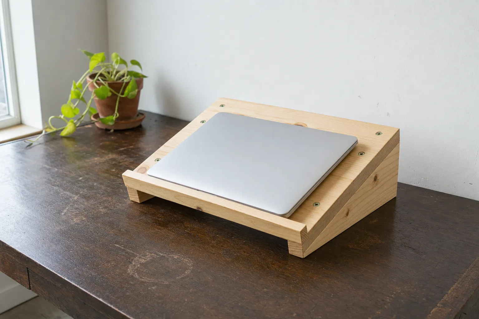
On a clean, fully cured surface, attach one equal-thickness non-slip pad near the front and rear of each Side Support's bottom edge, inset equally from the edges. Set the empty stand on the desk and confirm all four pads contact without rocking or sliding. Set the laptop on the Deck and let it settle forward (downhill, toward the low front end) until its front edge or front feet rest against the Front Lip, with cables slack. The Front Lip (projecting about 0.75 in above the Deck) sits directly in front of the palm-rest area of a typical laptop base. Recheck your viewing position. Stop using the stand if it rocks, slides, cracks, loosens, or develops a joint gap; if an unusually smooth-bottomed laptop still slides past the Front Lip, do not rely on this stand for it.
Tips
- Cut both side supports from the same reference edge and check them against each other with a T-bevel before gluing — a small mismatch between the two throws off the whole incline.
- Support the long, thinning offcut through the entire angled rip cut. It gets thin fast near the tip and can pinch the blade if it isn't backed up.
- This stand fits laptops with a base depth up to about 9 1/4 in — roughly the 11-15 in class. Deeper 16-17 in laptops will overhang the front edge, so measure your laptop before you cut.
- Glue the front lip to the deck's top face only, not its end grain, so it stands proud as a stop instead of finishing flush.
- Use a stop-block or caul when clamping the sloped joint — clamping straight down on an angled joint can let the parts slide sideways.
FAQ
Will this stand fit my laptop?
It's sized for laptops with a base depth up to about 9 1/4 in, which covers most 11-15 in class laptops. Larger 16-17 in laptops are deeper than that and will overhang the front edge, so measure your laptop's footprint before building.
Why is there only one screwed joint and one glued joint?
The two side supports are glued and screwed to the deck's sloped edge for strength. The front lip only touches the deck's top face and carries no real load beyond stopping the laptop from sliding, so it's glued only — no screws near where the laptop rests.
What's the hardest part of this build?
The single angled rip cut on each side support. It's a long diagonal cut rather than a crosscut, so a circular saw with a straightedge, band saw, or guided jigsaw works better than a miter saw, which can only pivot for angled crosscuts, not make a long rip.
Do I need to match the two side supports exactly?
Yes — cut one first, then set a T-bevel from its finished angle and use it to check the second panel's marked line before cutting. That keeps the incline identical on both sides so the deck sits flat and doesn't rock.
Can I finish it any color I like?
The plan calls for an optional clear satin finish, but any indoor wood finish works as long as it's fully cured before you put weight on the stand. Skip it entirely if you prefer bare sanded pine.
Build it, guided every step
The Fixie iOS app turns this plan into a customized build for your exact space - pick your dimensions, get an auto-generated cut list, order materials in one tap, and follow the steps with 3D previews. Have something else in mind? Describe it or snap a photo and Fixie will design your own build from scratch - your first design is free.
Download Fixie on the App StoreMore beginner projects